
- Shunt line with smith chart generator#
- Shunt line with smith chart full#
- Shunt line with smith chart software#
- Shunt line with smith chart series#
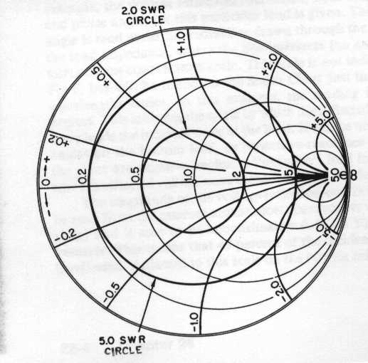
Furthermore, the SMITH CHART provides the ideal medium for visualization of the principle of operation of such transformers and for quantitatively determining their specific design constants.This problem will be solved with and without using the Smith chart. This means that the shunt suscep- tance must move us from yL to the 1 + jx circle on the admittance Smith chart. yL 1 zL 0.4+j0.8 Now locate the points where the SWR circle intersects the. The point of intersection is the normalized admittance yL (which we also could have calculated, but it’s faster to use the Smith chart). Draw a line fromzL through the origin and back out through the SWR circle. These devices are described in some detail herein since it is through its terminations alone that the transmission characteristics of waves along any given waveguide can be controlled. reactance to cancel jx and match the load. Locate zL on the Smith chart and draw the SWR circle. Open Circuit: Begin by normalizing the impedance parameters: Plot this zL on the Smith chart and use a compass to create an SWR circle.
Shunt line with smith chart series#
Slug transformers, on the other hand, are sections of line of appropriate characteristic impedance (or characteristic admittance) and length connected in series with, and forming a continuation of, the main line. Like the name implies, a shunt stub of some unknown length will be placed in parallel with the transmission line at some point near the load, the parameters of which we will generate using a Smith chart. Matching stubs or building-out sections, as they are sometimes called, are sections of transmission line, frequently of the same characteristic impedance (or characteristic admittance) as that of the main line, and either open or short-circuited at their far end, connected in shunt with the main line at any one of several permissible positions in the general location where it is desired to provide the match. These include the single and the dual matching stub, and the single and the dual matching slug transformers. Noise circles can also be plotted in a similar manner. Gain, VSWR, Q, and Stability circles can be plotted easily by simply entering S-parameters and then choosing the corresponding menu items.
Shunt line with smith chart full#
In this area the full functionality of a Smith Chart can be utilized. generalized circles are transformed into generalized circles (note that a straight line is nothing else than a circle with infinite radius and is therefore. The addition of a shunt capacitor increases the. Adding series inductor increases the overall inductance and therefore moves the point along the red line (constant resistance), which keeps the impedance within the Forbidden Region. Several commonly used devices for obtaining a match at the load end of a transmission line will be described in this chapter. The Smith Chart Drawing Area is the central focus of the Smith Chart Utility. Suppose the impedance of a source lies in the Forbidden Region in the Smith Chart in the upper right (above). Waveguide Impedance and Admittance Matching
Shunt line with smith chart software#
This edition includes a new chapter with example designs and description of the winSMITH software accessory. The last step is to determine the shunt reactance that will remove the reactive. The text provides tutorial material on transmission line theory and behavior, circuit representation on the chart, matching networks, network transformations and broadband matching. On the Smith Chart, we start from the load impedance and add a line. This classic reference book describes how the chart is used for designing lumped element and transmission line circuits.

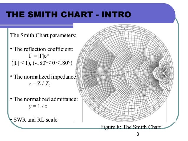
A horizontal line through the center of the main. It covers the history, development and applications of the Smith Chart. The Smith chart is made up of multiple circles, and segments of circles arranged in a way to plot impedance values in the form of R ± jX (Fig. Using a Smith Chart, evaluate the line for stub tuning using shorted series stub.
Shunt line with smith chart generator#
A generator with R o 75 is connected to a complex load of Z L 100+j100 through a transmission line of arbitrary length with Z o 75 and v p 0:8c. Smith, the originator of the Smith Chart. Smith Chart - Stub Matching Networks 1.Consider the circuit below. Compute the required circuit Q by (1 + Q2) m, or 3 L I F1. This is the second edition of Electronic Applications of the Smith Chart, written by Phillip H. This Lecture: Smith Chart and S-Parameters Quick notes about matching networks Smith Chart basics Scattering Parameters EE142-Fall 2010 4 Matching Network Design 1.


 0 kommentar(er)
